Building a delay module
Ever since getting into synths I’ve wanted a delay module. The Erbe-verb is very nice, but I wanted to build one (and not spend close to $500 on a delay). I have a collection of four guitar delays, two that I plug my synths through, and wondered about taking one of those apart and retro fitting them into a module. Then I stumbled upon the Echo Blue kit. It had all the things I look for in a delay pedal, including that dirty “analogue” sound, and only cost £36! I ordered one, built it (apart from the pots and the power) then scratched my head as to how to add CV control to it.
I wanted to be able to control all four controls (Mix, Delay, Feedback & Dirt) by CV (e.g from an LFO). Reading around it seemed that optocouplers would do the things I wanted, so I wired one up into the circuit to control the delay length and, to my surprise, it worked!
It only bloody works! Very pleased with this :) https://t.co/5b7F4qNLFw
— Simon /\/\e†s0|\| (@drsm79) April 12, 2016
Flush with success I even made a wooden panel for it:
Project delay pedal to synth module starting to look legit #Hipstamatic pic.twitter.com/fAe6aLuHkF
— Simon /\/\e†s0|\| (@drsm79) March 9, 2016
and then the thing just sat there unfinished. For months.
Optocouplers are a light sensitive resistor (photocell) attached to an LED. As you increase the voltage to the LED it gets brighter, decreasing the resistance from the photocell. The photocell resistance is high when the LED current is “off” and low resistance when the LED current is “on”. It’s this behavior that makes them useful for adding CV control to the delay.
The problem was wiring up the optocouplers in such a way as to A) make sense and B) not be too fiddly. I was soldering them onto the wires from the pots, which didn’t really work other than as a demonstration. I needed to get a board made that housed the optocouplers, jacks and possibly the pots and also provided power to the board.
And that’s where this page comes in!
Warning
This “project” is as much me learning as I go along as a concrete guide to making a delay module. I’ve never really done circuit design before, so this is very much a novice layout, and “patches welcome”.
Hopefully there’s enough information for someone to build a working module, and to reuse that experience to build others (I’m thinking of doing a chorus next…). Please raise issues in github for clarifications, ideas or improvements.
What you will need
- 1 x Echo Blue
- 4 x optocouplers
- 1 x 9v voltage regulator
- 5 pin right angle pcb header
- 6 Thonkiconn jacks
- Optionally 4 50kΩ pots (if you want to replace the ones that come in the kit)
- 1 LED
Steps
This is a work in progress…
First of all build the thing on a breadboard, to make sure you have the right things going into the right places. Then we’ll get onto making a PCB later…
- build the Echo Blue, but don’t solder on the pots or the power connectors
- put the 5 pin right angle header on the echo blue board, where the PCB is
marked
in/v/g/out/led- this is going to connect the Echo Blue to the “control board” - that will host the optocouplers, jacks and pots. - layout the board jacks, voltage regulator, resistor, LED and power pins
on the bread board like so:
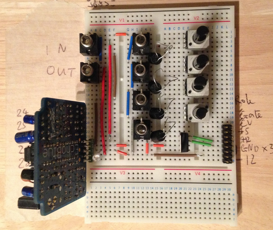
- use a multimeter and a simple voltage source to verify that your optocouplers are the right way round (the voltage will come from the jacks)